BEFORE READING:
- This article will walk you through setting your borders up in Skyline. If anything requires a deeper look or more explanation, please refer to the Glossary page linked below.
- BORDERS GLOSSARY
- NOTE: While setting up Borders, we recommend either using the perpendicular command, or have ortho on.
- You MUST "update" any changes you make to your Border
Removing Borders from the Project File
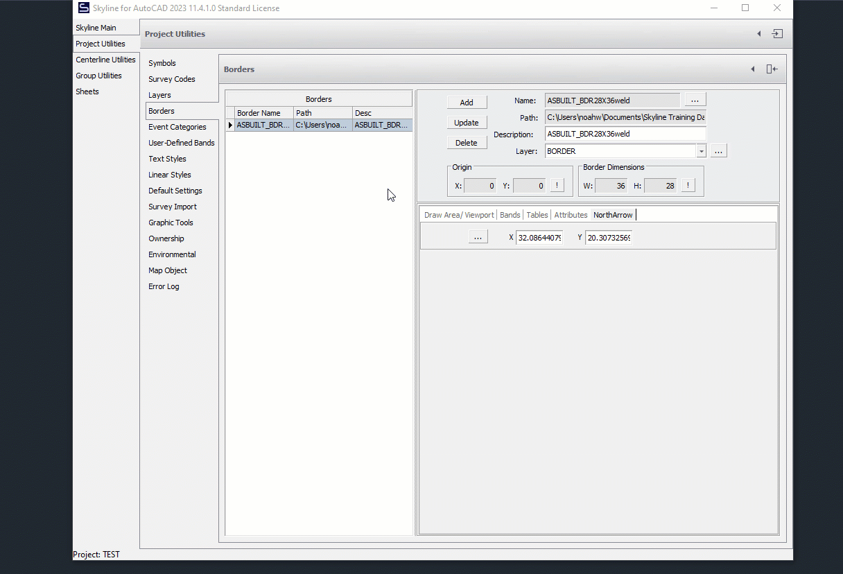
From Skyline’s main dialog box click the Project Utilities button/icon, then the Borders button. From this dialog box highlight the Border to be removed, and click the Delete Button.
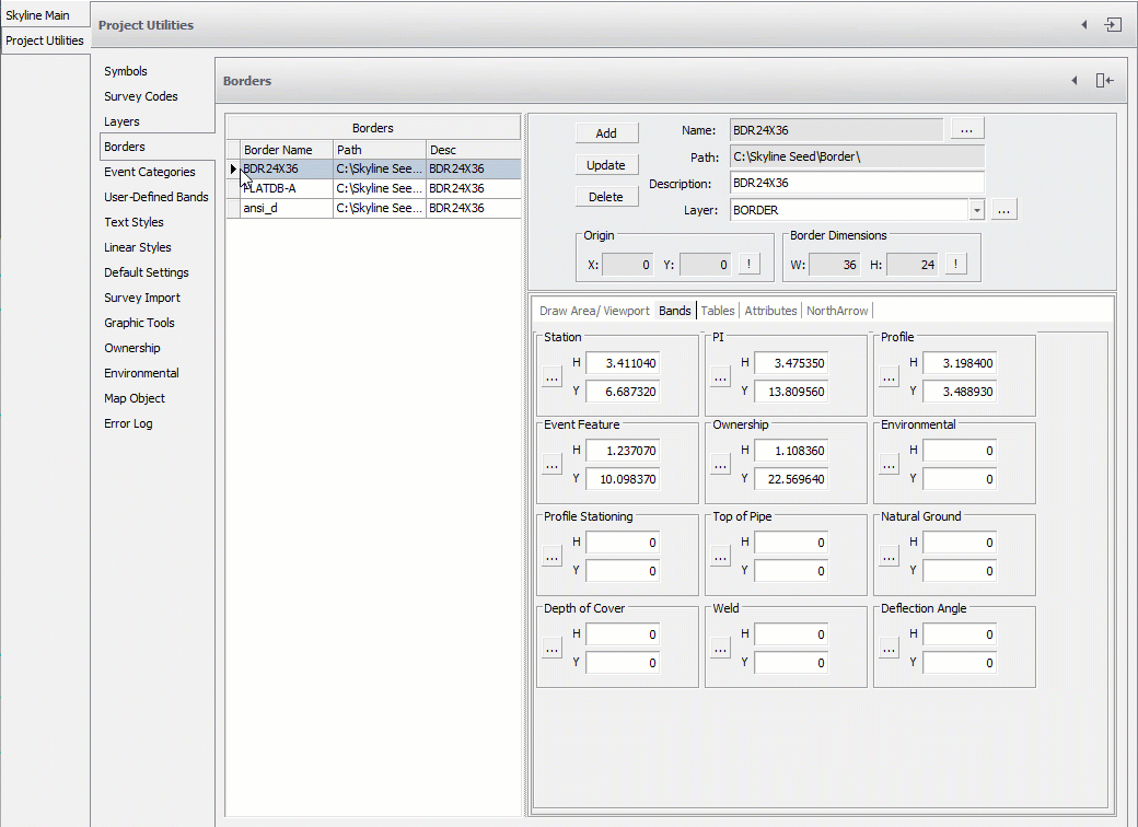
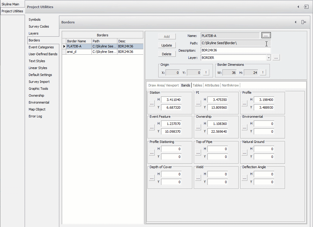
- The Name of the Border will be the same as the name of the file selected to be the Border.
- Click the Browse button to select the drawing file.
- Path to the Border drawing to be used and click Open. Skyline will automatically put the path of the drawing into the Path field.
- If the drawing is moved or renamed, but the Border is not updated in Skyline, an error will occur and Skyline will not be able to find the Border.
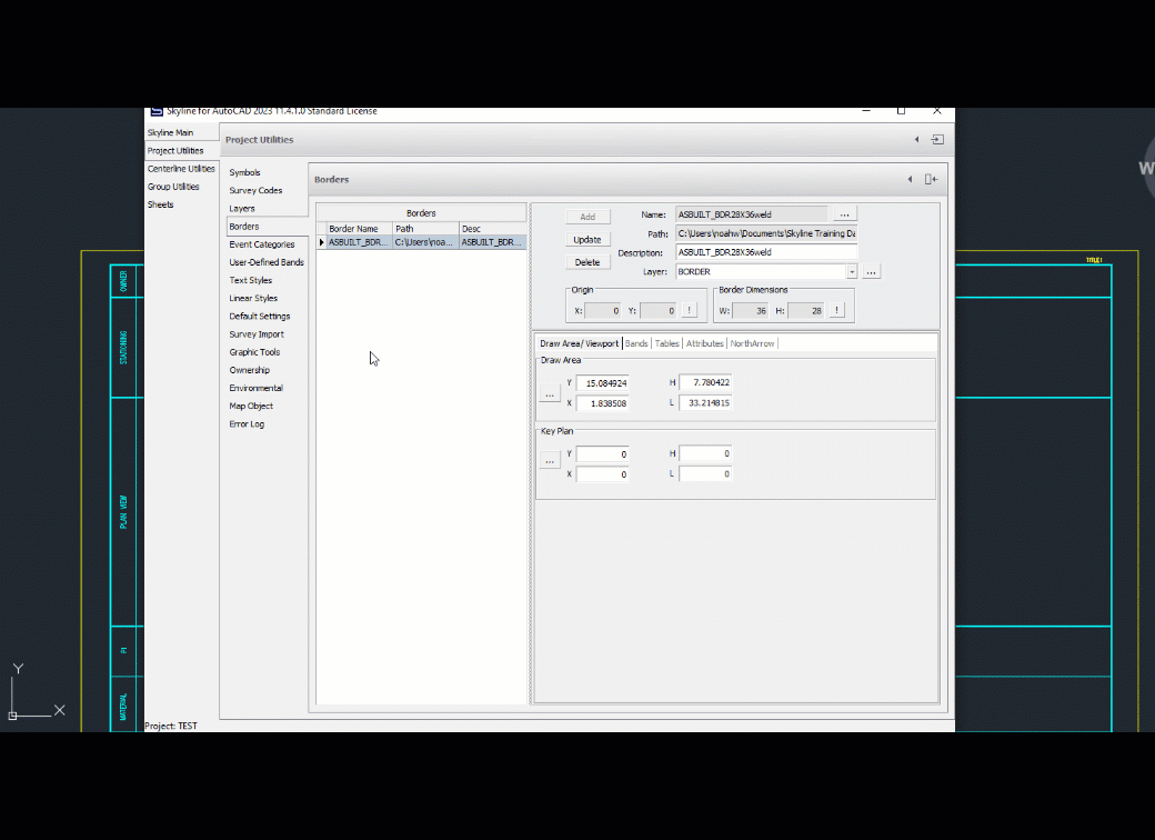
Define the Draw Area
The Draw Area is the location where the Viewport will be in the Border. Set the X-Dist, the Y-Dist, the Length, and the Height.
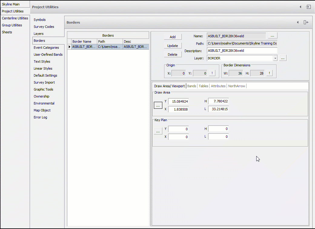
Define the Key Plan
Using the same instructions as above, you can set the location on the Key Plan.
The "Border Dimensions" box is not used to specify border dimensions, but to quickly and easily check what the dimensions are.
- Station
- PI
- Material
- Pipe
- Property
- Environmental
- Profile
If a Band will not be displayed on the Alignment Sheets, then it will not matter what the draw location is set to.
Note that when selecting the North Arrow location, you want to make sure that it allows for full 360 degree rotation without interfering with any of the linework in that band.
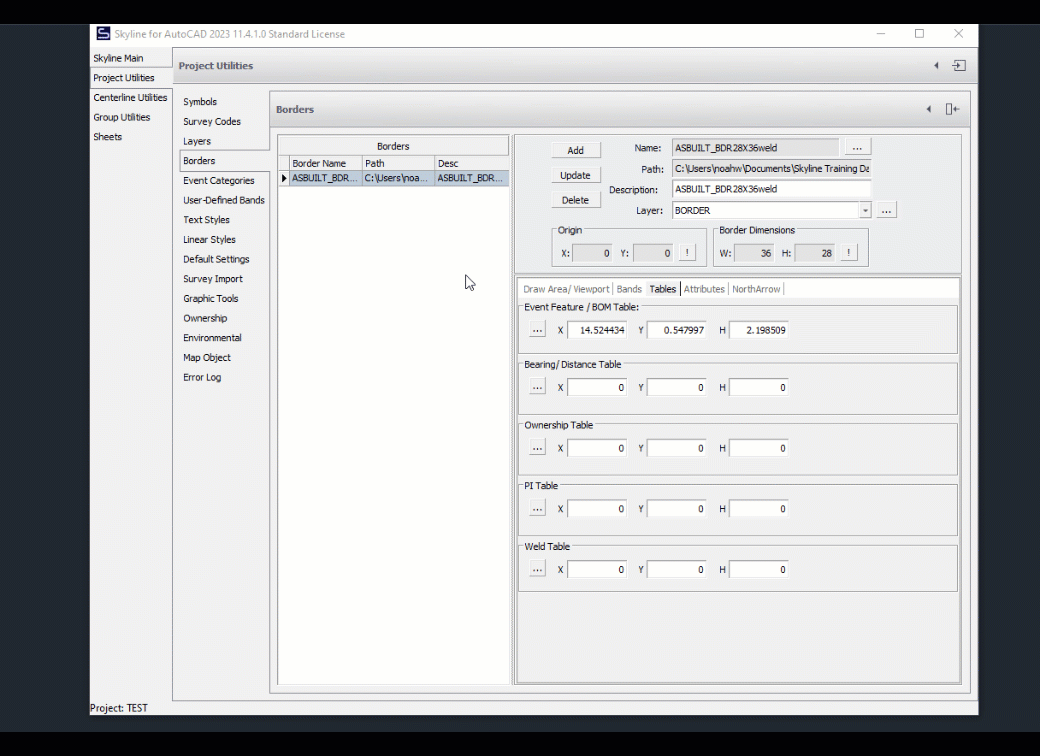
Setting Table Locations
Note that when setting Table locations, you first click in the upper left, and then lower right.
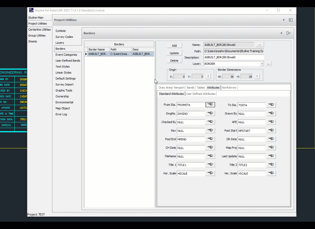
- For each field you can type in the name of the Attribute in AutoCAD.
Edited by Noah Waters 10/11/22